flexible printed circuit manufacturers
Printed circuit boards, also known as flex PCBs or flexi-circuits, consist of copper-based conductive patterns bonded to a thin insulating dielectric substrate. The base raw material is polyimide or polyester terephthalate (PET). The copper-clad laminates used in flex circuits are made from one to multiple layers of copper and a choice of adhesive-based or adhesive-less polyimide. In addition, a variety of other materials are incorporated to meet specific performance and assembly requirements.
The most important factor in designing a flexible printed circuit manufacturers is the base material, with the selection of the copper foil thickness and its adhesive layer playing a critical role in meeting the design goals for the flex PCB. This is because a higher layer count results in more complex and heavier circuitry, which increases manufacturing cost. For this reason, manufacturers strive to minimize the number of layers for maximum flexibility and performance.
A flexible circuit’s copper thickness, adhesive and the etching process all affect its performance and reliability. Thicker copper is preferred to reduce impedance and to improve conductivity, while thinner copper can be more easily formed into tight traces for better signal transmission. The copper must also be a high-conductivity alloy to minimize noise and distortion and enable efficient current flow, and the base material must be durable and stable in fluctuating temperatures.
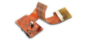
What materials do flexible printed circuit manufacturers use?
In many cases, the flex circuit will incorporate a FR4-based stiffener layer, which offers structural support to flex sections of the circuit board where they are most likely to experience bending stresses. Stiffeners are typically located in areas with high component density or for special applications such as stripline controlled impedance or radio frequency (RF)/electromagnetic interference (EMI) shielding.
Other components incorporated in the flex PCB are a conductive pattern, solder mask, and protective overlay. The conductive pattern, which is copper, represents the circuit traces that connect to the components. The solder mask prevents the copper from being exposed for soldering, while the overlay protects the traces from abrasion or chemicals. For high-reliability flex circuits, the overlay may be a fire-resistant halogen-free film.
Copper-to-copper contacts are typically plated with gold, nickel or silver. In some cases, a plated copper-silver contact is used to eliminate the need for solder. These contacts are used for high-speed communication and data transfer.
The most common flexible circuit material is Kapton, which consists of a polyimide substrate with one to several layers of copper. This material is naturally flexible and very tough, able to withstand significant tensile stress during manufacturing and use. It is resistant to heat, and it can withstand high-temperature reflow cycles and soldering.
The other main type of flex circuit material is a double-sided FR4. This is less expensive and has more flexibility than a single-sided flex PCB, but it requires more careful engineering and fabrication to achieve the desired results. It also does not offer the same degree of flexibility as a single-sided flex circuit. To achieve the required level of flex, a special coating is applied to the surface of the FR4. The coating is a low-stress adhesive that prevents damage during handling and assembly.